Features
- Supports multimode terminals
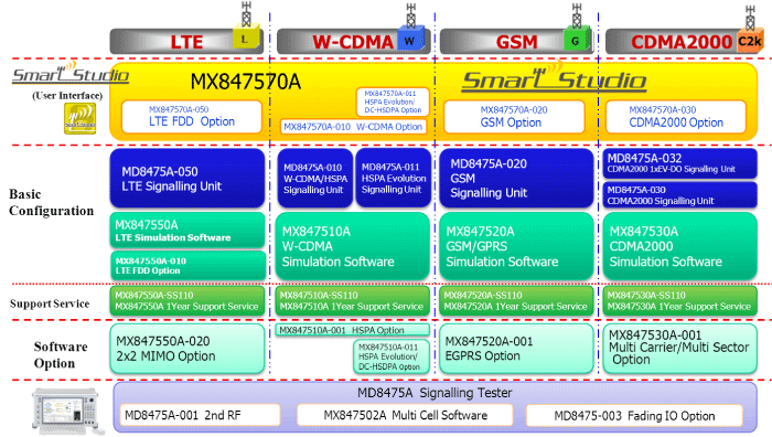
(LTE FDD (2×2 MIMO), W-CDMA/HSPA/HSPA Evolution/DC-HSDPA, GSM/(E)GPRS, CDMA2000® 1X/1xEV-DO Rev. A) - Simple operation software supports test conditions and service/call-processing function tests
- Built-in CFCS server function supports GUI-based IMS service tests, such as VoLTE
- LTE data throughput up to 100 Mbps (downlink) and 50 Mbps (uplink)
- All-in-One DC-HSDPA 43.2 Mbps Support
- Supports 2-cell test environment, including InterRAT Cell Reselection, Redirection, Cell Change, CS-Fallback, etc.
- Built-in PC with control and application server functions reduces benchtop footprint
Description
The MD8475A Signalling Tester is an all-in-one base station simulator supporting LTE FDD, W-CDMA/HSPA/HSPA Evolution/DC-HSDPA, GSM/(E)GPRS, and CDMA2000® 1X/1xEV-DO Rev. A. It supports service and call-processing tests for multimode LTE smartphones and mobiles with excellent cost-performance.
A full line of test environments are supported for the general mobile verification phase, such as max. throughput performance tests, stress tests, and battery consumption tests of multisystem LTE mobiles using 2×2 MIMO, as well as CS-Fallback, call connection reliability and stability tests at handover, communication tests at low RF power, and service verification using LTE Multiple PDN and SMS in a 2-cell environment*.
In addition, test conditions are easily set using the SmartStudio GUI, helping cut test environment configuration time.
*: Supports combination of LTE/LTE, LTE/W-CDMA, LTE/GSM and LTE/CDMA2000; requires two MD8475A units for testing LTE/CDMA2000.

Specifications
SmartStudio Test Functions
| Function | Description | LTE FDD | W-CDMA | GSM | CDMA 2000 |
|
| General | Location registration | ○ | ○ | ○ | ○ | |
| Out of service Setting | Sets BTS Power output to OFF and sets UE to outside NW condition | ○ | ○ | ○ | ○ | |
| Power Control for GUI | Power control for BS is changed into IDLE and Communication | ○ | ○ | ○ | ○ | |
| L1/L2 Countor | Measured values indicating the performance of Layer 1 and Layer 2 | ○ | ○ | − | − | |
| RF Monitor | The channel power, such as frequency, a frequency error and PDSCH, and PUSCH, is displayed | ○ | ○ | ○ | − | |
| Throughput Monitor | Actual data throughput can be verified at a fixed rate or at a rate determined by UE | ○ | ○ | ○ | − | |
| Trace view | The sequence of each layer is displayed on real time | ○ | ○ | ○ | − | |
| Voice/ Video Call |
W-CDMA GSM CDMA2000 |
UE originated/terminated voice call (Loop-back/Echo-back) |
Performs loop-back communication test*1 | ○ | ○ | ○ |
| UE originated/terminated voice call (Handset) |
Performs handset communication test | ○ | ○ | − | ||
| Emergency Call | Performs Emergency Call test with or without Test SIM*2 | ○ | ○ | ○ | ||
| Voice call released | ○ | ○ | ○ | |||
| Caller ID Setting | Performs Show ID/Hide ID/Unknown ID/Payphone/International call settings | ○ | ○ | ○ | ||
| Access Class Barred (Release99) [Barred] |
Bars all calls according to Release 99 standard | ○ | ○ | |||
| Access Class Barred (Release99) [Emergency] |
Bars all calls except emergency calls according to Release 99 standard | ○ | ○ | |||
| Access Class Barred (PSIST/ACCT) |
Bars all calls according to CDMA2000 | ○ | ||||
| W-CDMA | UE originated/terminated video call (Loop-back) |
Performs loop-back communication test*1 | ○ | |||
| Video call released | ○ | |||||
| Packet Connection |
IPv4 Packet test | Data supporting IPv4 can be sent and received | ○ | ○ | ○ | ○ |
| IPv6 Packet test | Data supporting IPv6 can be sent and received | ○ | ○ | ○ | − | |
| Packet Preservation/Dormant testing | Releases RRC Connection while maintaining PDN Bearer | ○ | ○ | − | ○ | |
| LTE FDD | UE originated/terminated SISO/MIMO packet call*3 |
Performs application tests utilizing packet data communications by connecting to server | ○ | |||
| SISO/MIMO packet call released |
○ | |||||
| Multiple PDN Bearer | Performs Multi Session packet communications test (Maimu 8 pass) | ○ | ||||
| W-CDMA | UE originated/terminated W-CDMA/HSPA packet call*4 |
Performs application tests utilizing packet data communications by connecting to server | ○ | |||
| UE originated/terminated HSPA Evolution/DC-HSDPA packet call*5 |
Performs application tests utilizing packet data communications by connecting to server | ○ | ||||
| W-CDMA/HSPA/HSPA Evolution/DC-HSDPA packet call released |
○ | |||||
| RRC Status Change | The mobile RRC Status can be changed during packet data communications (Cell DCH ⇔ Cell FACH ⇔ Cell PCH) |
○ | ||||
| UE originated PPP packet call | Performs PPP (Built-in server) packet data communication test (Not support Serial connection) | ○ | ||||
| PPP packet call released | Performs PPP (Built-in server) packet data communication test | ○ | ||||
| GSM | UE originated/terminated GPRS/EGPRS packet call*6 |
Performs application tests utilizing packet data communications by connecting to server | ○ | |||
| GPRS/EGPRS packet call released |
○ | |||||
| CDMA2000 | UE originated CDMA2000/ EVDO packet call*7 |
Performs application tests utilizing packet data communications by connecting to server | ○ | |||
| CDMA2000/EVDO packet call released |
○ | |||||
| Messaging | SMS transmission/reception | Performs SMS (7bit-ASCII, Unicode, Binary) test*1 | ○ | ○ | ○ | ○ |
| Continuous SMS Sending | Performs continuous sending of multiple SMS messages to UE | ○ | ○ | ○ | ○ | |
| MMS transmission/reception*8 | Performs MMS transmission/reception test | ○ | ○ | ○ | ○ | |
| 2-Cell Testing*9 *10 |
Cell Selection/Reselection (LTE FDD → LTE FDD) |
Performs Cell Selection/Reselection tests between two LTE FDD cells | ○ | − | − | − |
| Cell Redirection (LTE FDD → W-CDMA) |
Performs tests between W-CDMA system from LTE FDD system without continuous packet connectivity | ○ | ○ | |||
| Cell Change Order (LTE FDD → GSM) |
Performs tests between GSM system from LTE FDD system without continuous packet connectivity | ○ | ○ | |||
| CS Fallback (LTE FDD → W-CDMA) |
Performs tests between W-CDMA system from LTE FDD system for voice | ○ | ○ | |||
| CS Fallback (LTE FDD → GSM) | Performs tests between GSM system from LTE FDD system for voice | ○ | ○ |
*1: The opposite examination using two sets of move machines cannot be performed.
*2: Test USIM does not use by CDMA2000
*3: Requires MIMO option (MD8475A-001, MX847550A-020)
*4: Requires HSPA option (MX847510A-001)
*5: Requires HSPA Evolution/DC-HSDPA option (MX847510A-011)
*6: Requires EGPRS option (MX847520A-001)
*7: Requires 1xEV-DO option (MD8475A-032)
*8: Requires separate MMS application sever
*9: Requires 2nd RF option (MD8475A-001) and Multi-cell Software (MX847502A)
*10: Not support for CDMA2000
Specifications
| Items | Specifications |
| RF Connector | RF input/output connector (RF Main, RF Aux1, RF Aux2) Connector: N type, Impedance: 50 Ω, VSWR: ≤1.5 (500 MHz to 3 GHz) Reference oscillator Frequency: 10 MHz Level: TTL level Connector: BNC type Startup characteristics: ±5 × 10⁻⁸ (5 minutes after power-on, referenced to frequency 24 hours after power-on) Aging rate: 2 × 10⁻⁸/day, ≤1 × 10⁻⁷/year (referenced to frequency 24 hours after power-on) Temperature characteristics: ≤±2 × 10⁻⁸ External reference input Frequency: 10 MHz, Acceptable frequency range: ±0.5 ppm, Level: ≥0 dBm, Impedance: 50 Ω, Connector: BNC type |
| Transmission Characteristics | Frequency Frequency range: 350 MHz to 3.6 GHz Setting resolution: 100 kHz (Depending on MX847501A used) Accuracy: Based on reference oscillator accuracy Output level Level range: −130 to −10 dBm (Main, Aux1, Aux2) Resolution: 0.1 dB Level accuracy: ±1.0 dB (−120 dBm ≤ Output level, 350 MHz ≤ Frequency ≤ 3 GHz) ±1.2 dB (−120 dBm ≤ Output level, 3 GHz < Frequency ≤ 3.6 GHz) Signal purity Non-harmonic spurious: ≤−40 dBc (at ≥500 kHz frequency offset) Harmonics: ≤−25 dBc Modulation accuracy W-CDMA: ≤3.5% rms (with MD8475A-010, MD8475A-011) GSM: ≤1.5°rms (with MD8475A-020) LTE: ≤3.5% rms (with MD8475A-050) CDMA2000 1X: ρ >0.995 (with MD8475A-030) 1xEV-DO: ρ >0.995 (with MD8475A-032) |
| Reception Characteristics | Frequency Frequency range: 350 MHz to 3.6 GHz Setting resolution: 100 kHz (Depending on MX847501A used) Level Maximum input level: +35 dBm (Average) Input level range: −60 to +35 dBm (with MD8475A-010, MD8475A-011, MD8475A-030, MD8475A-032, MD8475A-050) −30 to +40 dBm (in-burst average power) (with MD8475A-020) Reference level: −60 to +35 dBm Variable range Rx level setting resolution: 1 dB |
| General | Display: Color TFT LCD screen, 12.1 inches (wide type), 1280 × 800 dots External interface Trigger I/O: BNC Call Proc Timing I/O: 15-pin mini D-Sub connector Call Proc Serial I/O: D-sub connector, RS-232C level Call Proc Ethernet A: RJ45 connector, 10/100/1000BASE-T level Call Proc Ethernet B: RJ45 connector, 10/100/1000BASE-T level Handset: RJ-11 connector Headphone: 3.5-mm dia. headphone jack Microphone: 3.5-mm dia. microphone jack USB: USB2.0, Type A, 4 ports RS-232C: D-sub connector, conforms to RS-232C GPIB: IEEE488 connector VGA: Mini D-Sub connector Ethernet: RJ-45 connector 10/100/1000BASE-T, 2 ports |
| Power Supply | 100 Vac to 120 Vac (±10%)/200 Vac to 240 Vac (−15%/+10%, Max.: 250 Vac), 50 Hz to 60 Hz (Rating), ≤480 VA (Max.) |
| Dimensions and Mass | 426 (W) × 221.5 (H) × 398 (D) mm (excl. protrusions),<25 kg (with all options) |
| Temperature Range & Humidity | Operation: +5° to +40°C, Storage: −20° to +60°C, ≤90% (no condensation) |
| EMC | EN 61326-1, EN 61000-3-2 |
| LVD | EN 61010-1 |


